
Designed by Scott Helmke
![]()
Assembly Instructions
* Soldering is a dangerous activity, involving both toxic chemicals and very hot materials. *
We recommend that you do not assemble this kit unless you have appropriate training and equipment, and use personal protection equipment such as eye protection.
1) Installing resistors, R2 and R3 values / color codes
Start by installing the resistors. R1 should be obvious enough, as that is the largest resistor. R2, next to the transistor, is the 47K resistor (Yellow – purple – black – red – brown), and R3 is the 10K resistor (Brown – black – black – black – brown).
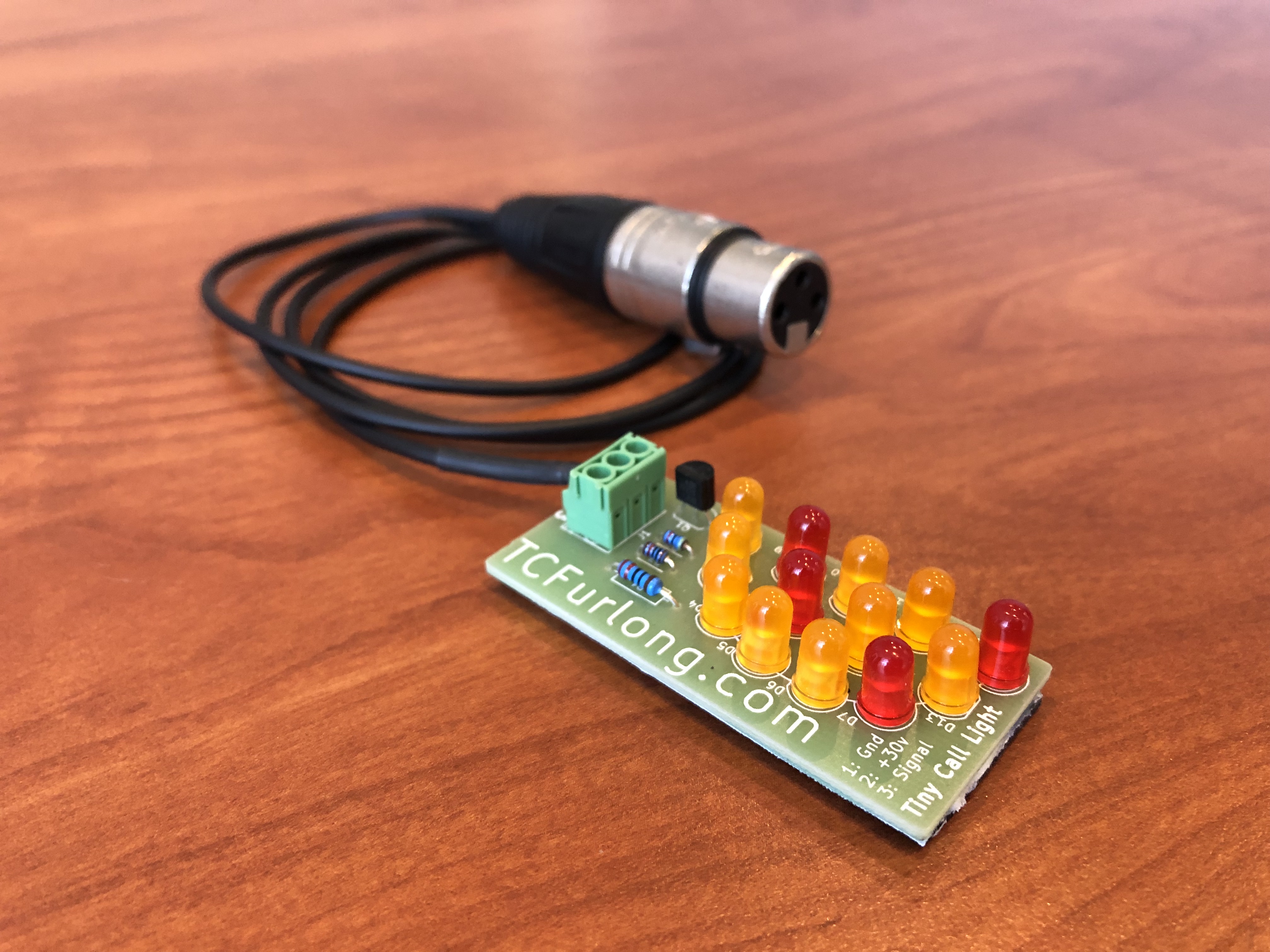
2) Installing LEDs
Install the LEDs next. It’s very important that you get the orientation correct, as they will not work backwards and even just one installed backwards will prevent the whole thing from working. There is a flat spot on the side of each LED’s base, which will match the shape of the LED outline on the circuit board.
Also very important is to make sure each LED is firmly seated against the circuit board while soldering. If there some space between the LED and the circuit board, it will be possible to cause damage to the printed circuit traces later.
If you want to try using other colors of LEDs, be aware that different colors have different forward voltage characteristics and will probably require changing the value of R1 or even using less LEDs.
3) Installing transistor and connector
Install the transistor next, making sure its orientation matches the outline on the circuit board. Finally, install the connector so that the holes for the wires faces out. Make sure this part is also firmly pushed against the circuit board while soldering.
4) Wiring for XLR
The numbers shown on the circuit board are the same as the XLR pin numbers, and follow the usual standard of having ground on pin 1, power (roughly 30 volts DC) on pin 2, and signal and call on pin 3.
5) Testing with 9v batteries
If you don’t have an intercom system handy to test with, you can use a stack of three 9 volt batteries to provide 27 volts for pin 2. Then just use a wire to connect pin 3 to the first 9 volt battery to provide the call signal.
6) Protecting the backside
You should protect the backside of the circuit board from stray contact with metal surfaces – making contact to a metal surface could damage the Tiny Call Light and/or other equipment.

Parts List
1x 220 Ω (R1)
1x 47K Ω (R2)
1x 10K Ω (R3)
1x KSP2222 (Q1)
13x LED (D1-13)
1x terminal block (J1)
1x 3′ mic/line cable
1x XLR female connector
1x Magnetic backing material