Education

by Scott Helmke

Welcome to the first in a series of posts about the practical theory for successfully using wireless microphones. Because this is such a big topic we’ve decided to break it into a series of smaller chunks, so stay tuned for future articles in this series.

How Does a Wireless Mic Work?

A wireless microphone works by transmitting a radio signal from the microphone (also called a transmitter) through the air to a nearby receiver. Each transmitter must have its associated receiver, which takes the radio signal and turns it back into audio so that it can be connected to an audio system. This works great and doesn’t require much thought, as long as you only have one microphone and receiver to work with. Each channel (one transmitter, one receiver) of wireless must have its own frequency to avoid interfering with other channels. The very cheapest of wireless systems don’t allow any tuning of different frequencies at all, while inexpensive systems have the ability to tune, but over a limited range. Professional shows that have a lot of wireless channels use the most expensive wireless systems, which are designed to have a wider tuning range and to work better in large systems. While we’ve used wireless microphones as an example, the same concepts apply broadly to all production wireless systems (IEM, wireless intercom, etc.).

What Else is the RF Spectrum Used for?

Beyond the need to simply have each wireless channel on its own frequency, the space that most wireless microphones work in is already filled with other transmitters, in particular television stations. The reason for this is mostly historical – before digital television (DTV) became available, analog TV stations had to be spaced apart from each other. In the USA every TV channel (both analog and digital) is assigned 6MHz of space in the frequency spectrum. VHF stations are assigned 54-88MHz and 174-216MHz, while UHF stations are assigned 470-608MHz. Early wireless microphones in the TV bands tended to use VHF frequencies, but eventually as technology improved the UHF band became the most popular space for microphones. The frequencies in the UHF band tend to work well for wireless microphones, allowing small antennas but still good distance – if you watch old concert films you might see some rather large antennas in the background for the VHF microphones. Joni Mitchell’s “Shadows and Light” film shows an antenna about 6’ tall right behind her onstage, to pick up the signal from her wireless guitar transmitter.

The open spaces between TV stations has generally been the most open space available over the whole frequency spectrum, and almost all of the rest of the spectrum has been claimed, assigned, and jealously guarded for other uses. There are a few safe spaces that have been designated as available for wireless microphone use, but almost all of the products currently available use the UHF band. But as analog TV has been replaced by digital TV, the need to provide empty space between stations has gone away. DTV stations can be packed tight together, leaving only enough room in between to fit possibly one wireless microphone channel. In the analog TV days a wireless microphone that had a tuning range of 30MHz could always find space between TV stations, since the TV stations had to be spaced out. The original UHF TV band went all the way up to 806MHz, most of it empty space.

What Does the RF Spectrum Look Like Today?

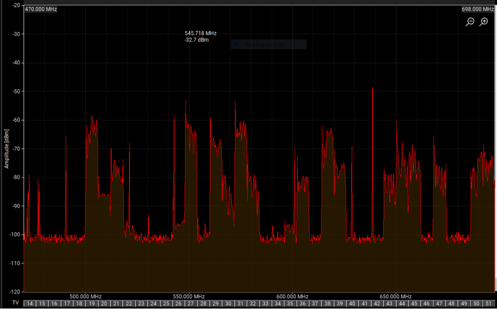
Here’s a scan taken in Chicagoland from 2017. All the blocks which look like city buildings are DTV stations. Any space in between those stations, aside from a small bit at the left of this scan, was legal for wireless microphones. You can see the TV channels at the bottom of the image:

Over the years the spectrum from 616-806MHz has been auctioned off by the government to companies for use in mobile phone and internet services. The TV stations that occupied that spectrum have been “repacked” into the remaining space, further crowding out wireless microphone use.

Here’s a scan from the same location from fall of 2020, after the most recent repack. The mostly empty space on the right side is now reserved for other services and not legal for wireless microphones. And some of the space at the left edge, channels 14 and 15, is not allowed for wireless microphones:

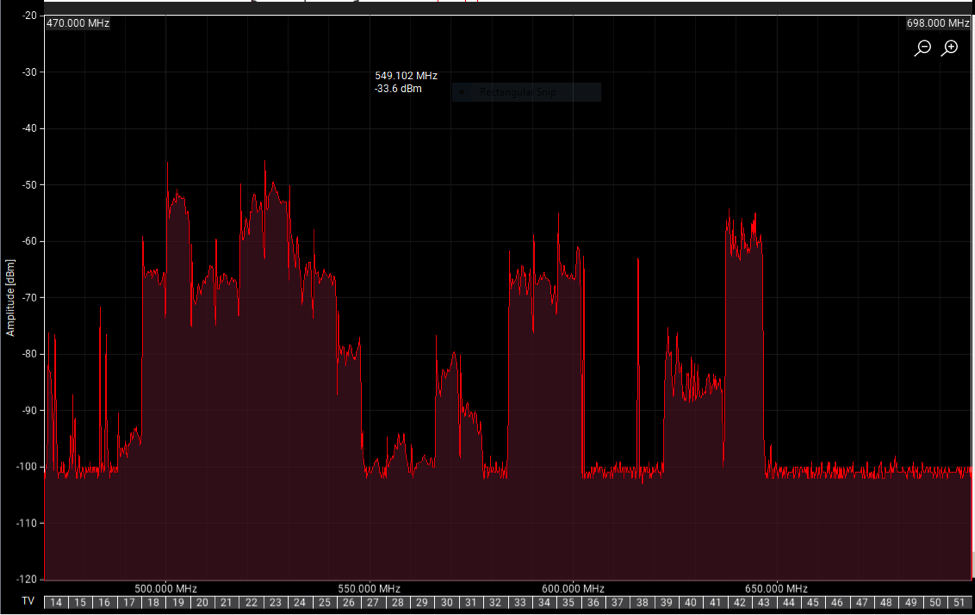
Back in 2017, before the latest auction and repack, there were roughly 17 open TV channels available in most of Chicago. Now, post-repack, there are only 9 open channels. Click here for more details on the 2017 FCC auction of the 600MHz band, and the 2020 repack.

What Does This Mean for You?

On to the practical. For finding good frequencies the first task is to figure out what TV stations are actually broadcasting in your area. Usually this can be done with manufacturer tools such as Shure’s Wireless Frequency Finder webpage, or their Wireless Workbench software. The ideal way to find all the local TV stations is with an onsite scan, which requires either a wireless mic receiver which can be networked to Wireless Workbench, or some radio scanning equipment. For just one or two wireless channels it’s enough to simply tune to a frequency not occupied by a TV station. And most modern wireless systems include some simple form of automatic frequency selection which can avoid active TV stations.

Finding good frequencies for a larger number of channels will be coming up in a future post. Stay tuned!

Stay tuned for the next article in the series. Next week’s topic: alternatives to UHF wireless. What other frequency bands are available for wireless users, and when should you consider them? Check back in for the answers.

Interested in purchasing a wireless system? Reach out to our Sales Team at 847-367-9588 or sales@tcfurlong.com for help selecting the right system for you.

We also carry hundreds of channels of wireless in our rental stock, and our experienced Project Managers can help design and implement a wireless system for your next show. Reach out to them today at 847-367-9588 or rentals@tcfurlong.com to get started.

MAPP 3D is latest evolution of Meyer Sound’s Multi Acoustic Prediction Program that launched over 20 years. The newest edition of the free loudspeaker system design and prediction tool adds 3D modeling and prediction to the already powerful legacy of design tools. We gave an introduction to the software in a previous blog, but we wanted to share some of our favorite tips and features to improve workflow.

Our project managers and sales engineers regularly use the proven and essential tools in MAPP 3D as part of our “Better Audio by Design” philosophy of creating custom tailored solutions for every project. Whether deciding the necessary height and down-angle for point-source speakers in small ballrooms, or complex outdoor multi-zone systems, the tools in MAPP 3D are scalable for any design.

One major advantage of the MAPP 3D workflow is the availability of all of the necessary design tools on a single screen. The Model View tab gives you quick access to several virtual camera angles, and the Object and Processor settings are just a click away to modify loudspeakers, microphones, and other objects in your design. Lastly, the Measurement View displays broadband response and maximum acoustic output, including transfer functions based on room and processing interactions.

Here are some of our tips to get the most out of your MAPP 3D user experience.

1) Import your drawings

While MAPP 3D includes a pallet of tools to create three dimensional drawings, it also has the ability to import existing 3D drawings into the software, allowing significant time and cost savings for building complex venues within the software. MAPP 3D supports the importing 2D and 3D AutoCAD (DXF) and 3D Sketchup (SKP) files. While importing SKP files is fairly straightforward, Meyer Sound does have some suggestions for preparing DXF files before importing (read more about them here).

Once in MAPP 3D, users can turn layers on and off from your imported venue. At this point, prediction planes will still need to be assigned, but tools like “snapping” allow for easy addition of prediction plane geometry directly to the imported files.

A bonus tip is to always verify the scale of the model after it has been imported by using the Distance Tape Measure tool. Accuracy of the venue model is essential when designing a sound system for a given space.

2) Download updated speaker data

Meyer Sound has worked to meticulously catalog their loudspeaker data, and each 3D loudspeaker performance is based on more than 65,000 three-dimensional measurement points taken in 1/48th octave resolution in Meyer’s own anechoic chamber in Berkeley, California. All of that data is available for download through the HELP > CHECK FOR UPDATES menu.

It is worth noting that the initial installation of the MAPP 3D software only includes a limited pool of loudspeakers to add to a design, and this is the menu where users will choose additional speakers to download to your computer. Meyer Sound has continued to update the available loudspeaker data, including support for legacy models and additional array configurations for select point source boxes.

3) Take full advantage of the Measurement View

While viewing 3D pressure plots of prediction planes can give some general information of coverage, including hot and dark zones of a loudspeaker system design, MAPP 3D’s Measurement View lets users dive much deeper. After placing virtual “microphones” within the venue, users can evaluate broadband response and maximum acoustic output in this tab. Pioneered by Meyer Sound, SIM (Source Independent Measurement) is a technique for real-time acoustical analysis, and this virtual SIM system is built right into the MAPP 3D to help users optimize processor settings during the design phase.

The default view displays four charts and includes transfer functions for four measurements: result amplitude (between processor input and microphone), result phase (between processor input and microphone), room and processor amplitude (between the processor input and microphone and between processor output and microphone displaced on the same plot), and the IFFT (signal generator and microphone difference).

Additionally, the Headroom tab gives a peek into SPL predictions at each microphone location and the available headroom predictions for individual loudspeakers. This helps designers avoid over-designing systems and can lead to greater cost efficiencies.

4) Sync your GALAXY device

Meyer Sound’s series of Galileo GALAXY networked audio processors provide precision control of loudspeaker management parameters including EQ, delay, and matrix mixing. MAPP 3D now offers full workflow integration with GALAXY system processors, enabling users to load resultant EQ and filter settings derived from predictions directly into multiple GALAXY processors.

Once the software and processors are synced, settings can be pushed in either direction. This means users can tie predictions and system tuning together in the same workflow, simplifying the need for additional software. Paired with the ability to make virtual SIM predictions, much of the loudspeaker optimization can be handled offline.

Conclusion

MAPP 3D is a great tool for all levels of loudspeaker system design. If you would like to learn more, join us for our MAPP 3D Webinar on Tuesday, March 30th (sign-up here). Meyer Sound also has a great resource of help topics available at mapp-3d-help.meyersound.com/

Our loudspeaker system Design & Alignment team have decades of experience and can help design the perfect loudspeaker system for your next rental, live event, or permanent installation. Email align-design@tcfurlong.com today with questions.

Immersive audio (also called 3D audio, 360° sound, spatial sound, among others) is one of the fastest growing areas of innovation and experimentation in the live sound industry. Just about every major loudspeaker manufacturer has made forays into developing immersive audio technologies; as those solutions become more affordable and widely available, we’ll see them implemented in venues of all shapes and sizes. But what exactly is immersive audio? How does it differ from traditional loudspeaker systems? In this article, we’ll give an overview of this emerging technology.

When most of us read “immersive audio,” the first connection we make is likely to surround sound. Just about everyone has heard a surround sound system, whether at a movie theater or in their own home. While a traditional X.1 surround sound system allows a mix engineer to pan sounds around the audience in the horizontal plane, an immersive audio system with the proper loudspeaker deployment allows the engineer to position tracks in the vertical plane as well, allowing for ‘3D’ audio that the listener perceives as coming from any number of points around them in physical space.

It’s also important to note that immersive audio systems don’t have to be used strictly in surround-style deployments; traditional Left/Right or LCR loudspeaker hangs can also benefit from immersive audio technology. In live performance applications where a realistic soundscape is desired, immersive audio systems allow you to localize sound sources more precisely than typical stereo panning and delay. When done properly, the audience will perceive the sound as coming directly from the performer on stage, effectively masking the fact that any sound reinforcement is happening at all.

How are these results achieved? As with most emerging technologies, the terminology used to describe immersive audio systems can vary pretty wildly between manufacturers. However, the phrase “object-based mixing” is a common thread across most platforms. In object-based mixing, an engineer can place a sound “object” (which could be an individual audio track or a stem of multiple tracks) within a virtual 3D environment represented within the chosen software. A system processor then runs the information from the software through a complex digital matrix to ensure the right level of each audio source is sent to each loudspeaker with the correct delay times. In turn, the listener will perceive the sound source as coming from a specific point in space around them.

While most immersive audio systems require the use of a special system processor that’s purpose-built for immersive applications, strides have recently been made to allow for immersive audio mixing using existing platforms. Meyer Sound’s new Spacemap Go software utilizes the processing power of their existing Galileo GALAXY processors. This means that the hundreds of venues around the world that already utilize the GALAXY platform for system processing now have access to immersive audio mixing with Spacemap Go via a completely free update. “Spacemap Go now gives users an affordable, scalable, and flexible path into immersive audio without compromising the features needed in a live production environment. This new tool works with any loudspeaker arrangement for any live audio application, including live mixing,” according to Meyer Technical Support Specialist Josh Dorn-Fehrmann.

The possible applications of immersive audio technology extend to all corners of the live sound world. In theatrical performances, where small loudspeakers might previously have been hidden in scenery, sound effects can now be pinpointed anywhere on the stage. A classical musician can perform a solo that the whole audience can hear clearly, without realizing that a loudspeaker system is in use at all. In pop music performances, the sounds of instruments and effects can swirl around and over the audience in ways that weren’t previously possible. “Immersive audio provides a much broader canvas and tools for the mixer to use. There is a learning curve when coming from a stereo/mono world. We have to rethink and relearn,” says Dorn-Fehrmann. “It is up to the immersive system manufacturers to make this transition as comfortable and elegant as possible.”

As immersive audio systems become more widespread, and as manufacturers continue to push the boundaries of what’s possible with these systems, audiences will experience the work of their favorite artists in brand new ways. This modern day frontier of live sound technology will continue to be an exciting space for innovation in years to come.

Are you interested in the possibilities an immersive audio system would bring to your venue? Our loudspeaker system Design & Alignment team have decades of experience, and can work with all major loudspeaker manufacturers to design the perfect system for your space. Email align-design@tcfurlong.com today with questions.


By Scott Helmke

At TC Furlong Inc., we take pride not only in the size and scope of our rental inventory, but in the quality and reliable performance of the gear we offer. This means that every piece of gear we send out on a rental gets tested before it leaves the shop, and again when it returns, to ensure that our customers are getting gear they can always count on. In this article, TC Furlong engineer Scott Helmke lays out our process for testing IEM earbuds in a way that is more objective and reliable than a listening test, and doesn’t require the additional sanitization steps that a listening test would.

Several years ago we realized that we needed some way of testing IEM earbuds that had been used as part of rental systems. The most obvious method, actually listening to the earbuds directly, had issues with sanitization and also with having a truly reliable test.

The next test method was to use a TOA speaker impedance tester through an adapter box. This test is still used with single-driver earbuds, as it is quick and simple to do as well as providing a good test. However, the impedance meter test is not useful for testing earbuds that have multiple drivers as the meter only works at one specific frequency. Since the multiple drivers in an earbud are usually used to cover different frequency ranges, an impedance test would need to work at several different frequencies to be effective.

For a while we went back to a version of the listening test, which was to use a measurement microphone and a small acoustic coupler (literally a block of wood) to feed the earbud sound into a test microphone. The person doing the testing would listen to the microphone through a pair of headphones, which made the listening test much easier and with no need for extra sanitization. However, it was still not a very accurate test.

Finally, we devised a system for directly measuring the impedance curve of an earbud driver across the whole frequency range, using Rational Acoustics’ SMAART software and a dedicated test box. This is not the same as measuring frequency response, of course, but it doesn’t require any special acoustic coupler or test mic – literally just some connectors, a resistor, and a switch. The test circuit sends pink noise from SMAART through a small resistor and then into the earbud under test. The inputs to a SMAART transfer function (a display which measures the difference between two signals across a frequency range) are the direct pink noise as reference signal, and the pink noise from where it leaves the resistor and enters the earbud as the test signal.

The theory of what is happening is perhaps a little beyond this blog article, but the result is a crude impedance curve of the earbud under test. This test does not show the true impedance curve, but it does give a repeatable test. An earbud with damaged driver(s) will show a different impedance curve than a good earbud of the same model, and so it is possible to measure a known-good earbud and use that as a reference for testing others of the same make and model. And small differences can be seen in the test – simply covering the earbud’s end with a finger will visibly change the displayed trace.

Finally, to make the test easier and cheaper to set up on multiple workstations, we started using a free application called Room EQ Wizard. This software, which is popular with amateur loudspeaker builders, includes an impedance test mode. The setup is very simple, the test signal is sent through a small sense resistor and then the earbud under test, and the signal voltage is measured at each side of the sense resistor. From those two voltages an impedance curve can be calculated and displayed. A small box with an ⅛” earbud jack and a switch to choose left or right earbud makes the test very easy to perform, and a PC with a stereo headphone output and a stereo line input jack is all the computer hardware needed.

As an example, below is a display of two traces (left and right on the same pair of Sennheiser IE4 earbuds). You can see slight differences, but the traces are closely matched. Reference traces can be saved as a file for later tests. Different brands and models of earbuds will have different traces than these.

Whether it’s a pair of earbuds, a full PA system, or anything in between, you can have confidence that every piece of gear you rent from us has been thoroughly tested to meet our standards. We won’t send anything out on a rental if we wouldn’t be confident using it on our highest-profile gigs. We also have strict sanitization procedures for all of our gear, to ensure the safety of everyone who uses it.

If you’d like more information about our earbud testing rig, or anything related to our in-shop gear testing and troubleshooting procedures, reach out to Scott at shelmke@tcfurlong.com.

 If you’re interested in renting an IEM system, or anything else from our extensive rental inventory, get in touch with one of our Project Managers at rentals@tcfurlong.com or by calling us at 847-367-9588.

Proper gain staging (or gain structure) is a critical skill for any audio engineer to develop, and arguably the single most important determining factor in the overall quality of a mix. Proper gain staging can lead to a mix that is clear, free of extraneous noise, appropriately loud, and with plenty of headroom. When gain staging is not done properly, the result can be a mix that is full of noticeable noises and hiss, not loud enough, or, perhaps worst of all, characterized by unpleasant distortion or clipping.

Gain management is of heightened importance in the era of digital audio. In the days of all-analog signal flows, overloading an individual gain stage would often be seen as a beneficial effect, imparting “warmth,” “punch,” or “fullness” on a signal. Unfortunately, the effects of digital distortion are far less pleasant on the ear, and care should be taken to avoid clipping in a digital signal chain.

A gain stage is any point in a signal chain at which the level of the signal can be altered. In this article, we’ll discuss gain staging from the perspective of using a digital console for live sound mixing, but many of the principles here are equally applicable to mixing in a DAW, or on an analog console.

#1: A Clean Signal At The Source Is Key

We’ve all heard some variation of the phrase “garbage in, garbage out” in reference to properly capturing audio at the source. This is especially important advice when it comes to gain staging. For example, if a lavalier or headset mic is improperly positioned to pick up a speaker’s voice, it may be necessary to crank up the gain on that channel, unnecessarily raising the noise floor. A vintage electric bass guitar’s pickups might have a weak output, necessitating the use of an active DI to bring the signal to an appropriate level for your mixer’s input. Similarly, some dynamic mics are known for their low output levels, and can sometimes benefit from the use of an additional phantom-powered ‘clean’ preamp. You’ll notice that the last two examples involve the addition of extra gain stages, which brings us to our next tip…

#2: Your Mixer’s Preamp Is Not The Only Gain Stage

At first glance, you might think there’s only one gain stage to worry about in the signal flow of any one channel: the knob labeled ‘GAIN,’ right? Of course, there’s a lot more to it than that. Thinking back to our previous tip, there are often multiple gain stages to consider in a signal chain before it even reaches the input of your mixer. In addition to the examples given above, wireless mic receivers usually have gain control, and it’s important to set the gain properly to deliver a strong signal to the mixer without distortion.

Gain structuring considerations don’t stop once a signal passes through your mixer’s head amp. While we don’t think of it as such, the channel EQ is a gain stage that deserves consideration. Whether you’re making additive EQ changes (i.e. boosting the gain of certain frequencies) or subtractive changes (i.e. cutting the gain of certain frequencies), you’re impacting the overall gain of the channel. Dynamics processors (compressors, gates, expanders, etc.) by their very definition have a huge impact on gain, and in fact most have a ‘makeup gain’ control – that is, yet another gain stage to take into account.

Finally, we come to plugins. While the use of hardware inserts in live sound applications becomes rarer by the day, the use of software plugins has exploded in recent years. Many digital console manufacturers have gotten into the plugin game themselves, offering plugin bundles for purchase alongside their hardware, or bundling them in for free with their consoles. The digital nature of plugins means they are often overlooked as a gain stage, but they have the same impacts on your signal as the analog hardware they are often designed to emulate. It’s important to take into account all of the gain stages a signal will pass through, to maximize headroom and minimize noise and distortion.

#3: Think About Optimal Fader Placement

To the untrained eye, a fader on a console looks like a tool that makes linear adjustments. In other words, no matter where the fader is positioned, moving it by one centimeter should have an equal impact on the signal level. Of course, we know that’s not the case; faders operate logarithmically. To put it into the simplest terms possible, faders are more sensitive to adjustments the closer they are to their ‘0’ or ‘Unity’ point. Thus, in order to have the most precise control over your mix, you should aim to structure your gain so that you end up mixing with all your channel faders near unity. Some engineers will even set all their faders at unity during sound check, and adjust levels with their gain controls to ensure maximum control when it comes to showtime. This practice isn’t strictly necessary, or even recommended by most, but it goes to show that optimal fader placement is worth taking into account.

#4: Leave More Headroom Than You Think You Need

‘Headroom’ is the difference in dB between the normal operating level of your channel or mix, and the point at which the signal clips. It’s tempting to decrease your available headroom and squeeze the maximum signal level possible out of your mix, but keep in mind that sudden, unexpected signal peaks are a fact of life in live sound mixing, for a variety of reasons. It’s better to have a slightly quieter signal overall, in exchange for avoiding the ugly sounds of digital distortion.

There’s more to think about in gain staging than first meets the eye, but by following a few simple principles, you can make the most of your gear by achieving optimum levels and maximum headroom with minimal distortion and noise.

TC Furlong Inc.’s engineers have the experience to make your next live event sound great. If you need top notch gear and technicians for your next event, get in touch with one of our Project Managers at 847-367-9588.

For more technical tips, sign-up for our email newsletter!