By Scott Helmke
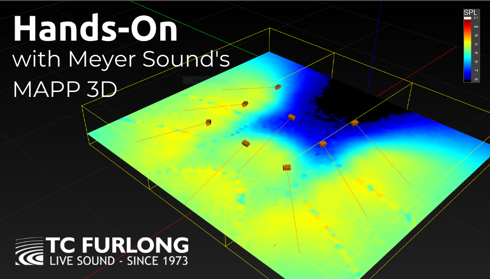
I am very happy to be able to report on the latest version of Meyer’s MAPP (Multi Acoustic Prediction Program), MAPP 3D. Meyer’s extremely accurate and reliable speaker system design and prediction software originally developed more than 20 years ago, now in a 3-dimensional version. Currently in pre-release, general release of this software is scheduled for August 19, 2020.
I’ve been using the previous 2D versions of this software to simulate various concert setups and determine the best choice of loudspeakers and how to deploy them. Many high-end loudspeaker companies have prediction software, but Meyer’s MAPP has stood out for years because of the extremely high accuracy and resolution of their speaker data and prediction software. Needless to say, being able to produce a trustworthy loudspeaker deployment is extremely useful. And now, the ability to predict loudspeaker coverage and SPL in a 3-dimensional space makes it even better.
Going 3D
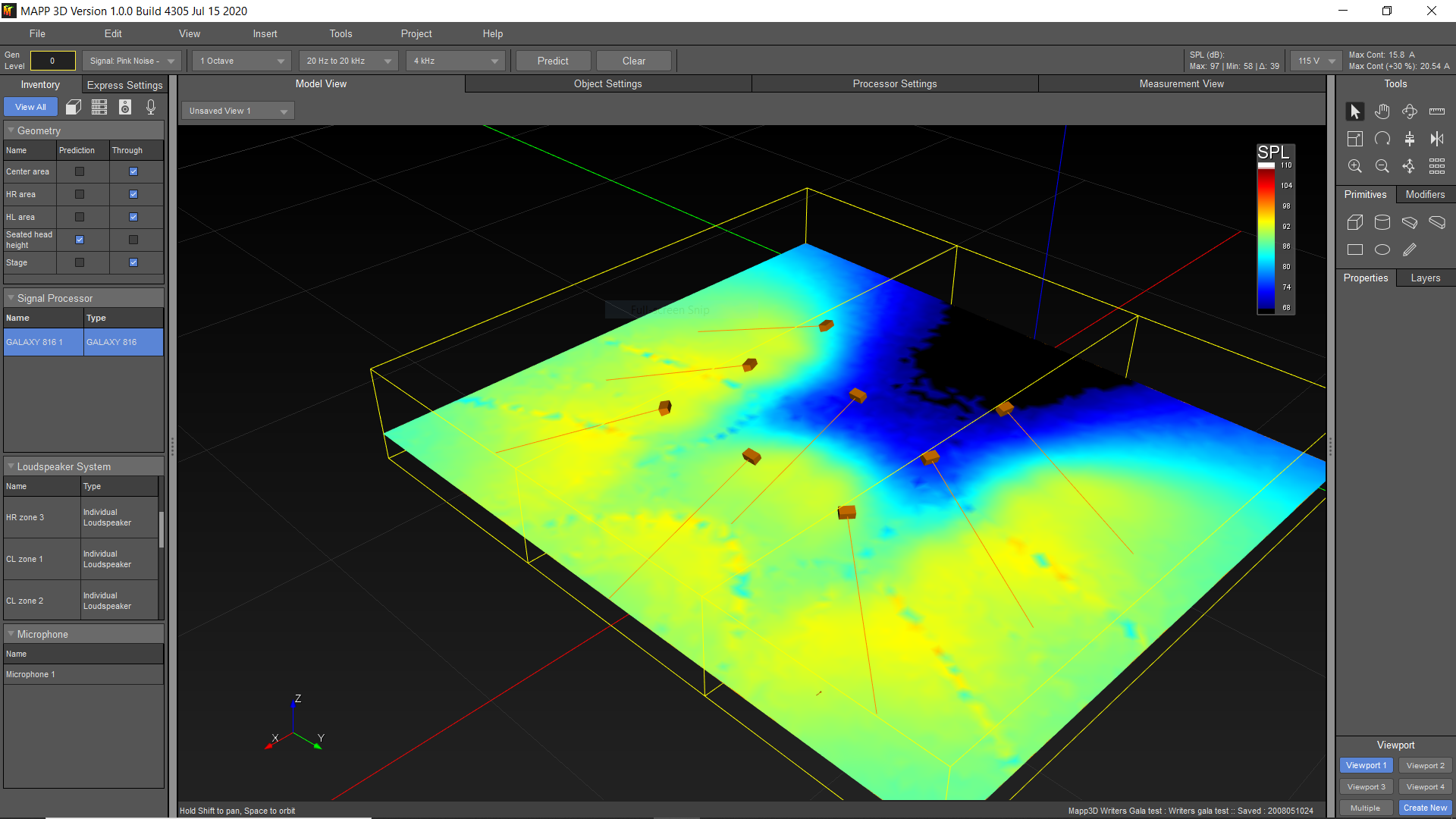
The earlier versions of MAPP allowed you to place virtual Meyer loudspeakers, individuals or in arrays, into two-dimensional projects in either a side or overhead view of a venue. For a theatre with angled seating areas you would use a side view, putting in lines to represent seating areas and using the software to predict relative volume and frequency response over those areas. Another design might use an overhead view to make sure the proposed loudspeaker system covered as well across the seating areas as well as up and down. MAPP 3D allows you to work in a CAD-like 3-dimensional space, placing objects within the 3D planes to represent seating/architecture, loudspeaker systems, and surfaces designed as prediction areas. The software will then show the spectrum of SPL levels as a color gradient across the prediction areas.
System Example
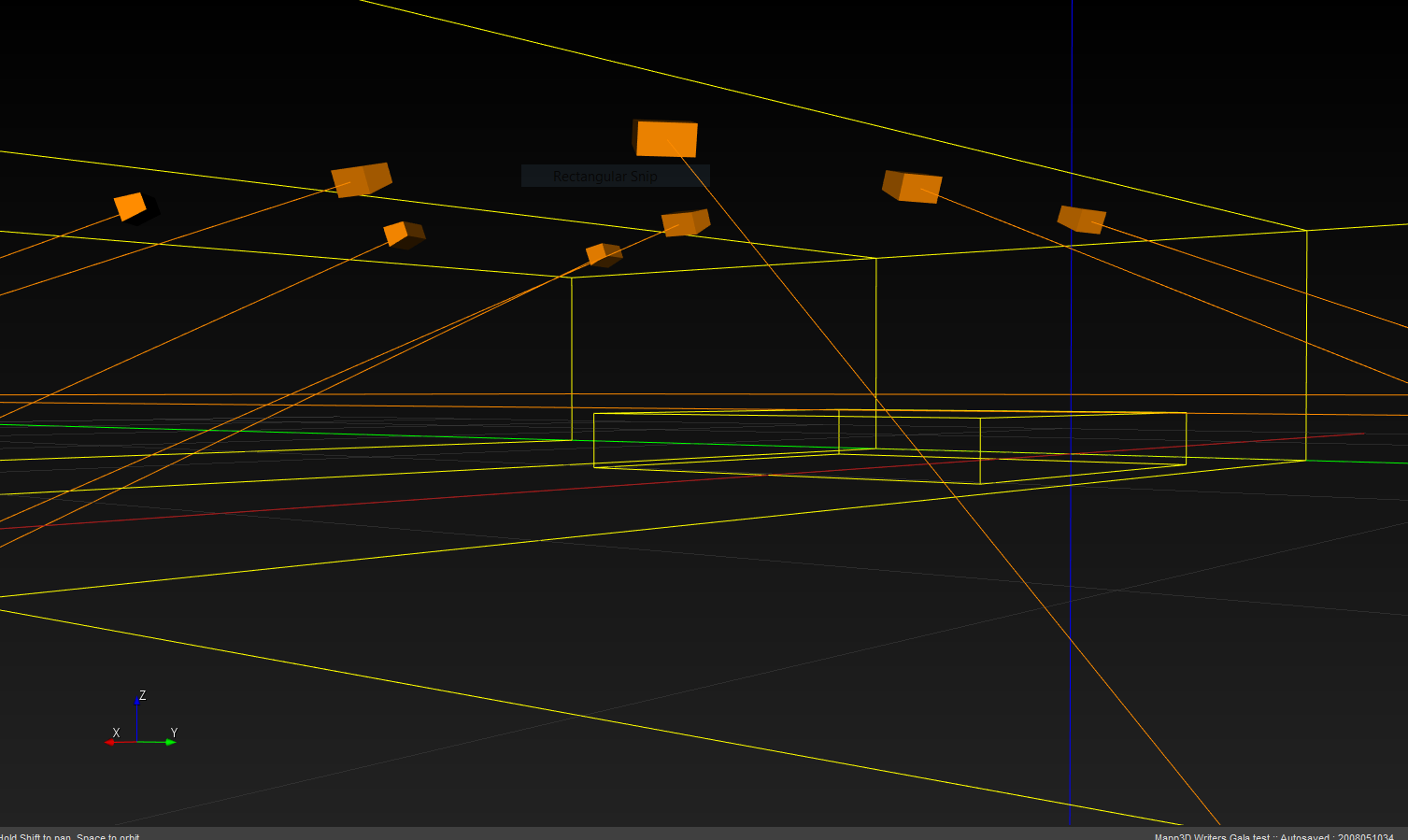
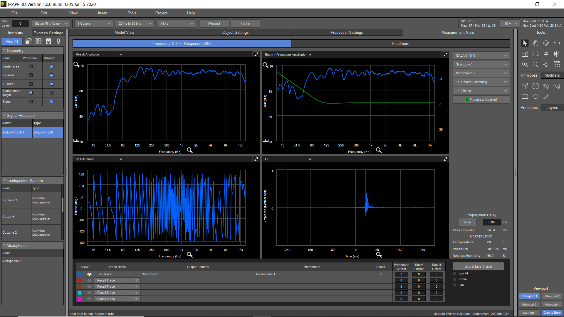
The simulated venue and loudspeaker system shown here is from an annual theatrical fundraising gala, usually produced in a hotel ballroom consisting of three spaces linked by airwalls. Speaker hanging locations are limited to airwall tracks in the ceiling, including one extra track that runs down the center of the middle section. The goal is even coverage over the seating area (many large round tables), with minimal spill onto the thrust stage. I’ve actually set the prediction plane to be a surface four feet above the floor, to approximate how it will sound to the average person sitting down. I was even able to move my virtual measurement microphone around to set delay times between speakers, saving time during setup.
Galileo and SIM3 Emulation
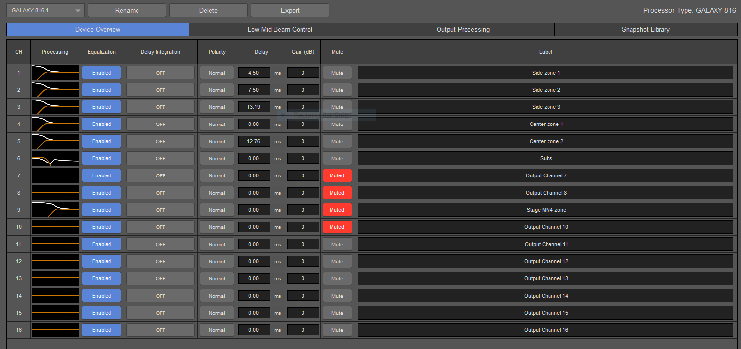
Since you wouldn’t deploy a large speaker system in the real world without a speaker processor, MAPP 3D allows you to do just that in the virtual system as well. Speakers can be assigned to outputs of a virtual Galaxy processor, and all of the signal processing can be applied to the simulated response – ultimately you could send those settings to a real processor before even loading the truck, and have a great starting point for tuning the speaker system in the actual venue. It’s also possible to put one or more measurement “microphones” into the 3D area and see a simulated Meyer SIM3 frequency and phase response display.
Additional Features
While the MAPP 3D software provides basic 3D CAD functionality for putting in simple shapes and prediction areas, it also allows 3D CAD files in DXF and Sketchup formats to be imported. It is still necessary to define prediction surfaces, but having the actual architecture to use as a reference will save a lot of time and also allow a better-looking output. There are also advanced tools such as a line array auto-splay tool to help quickly set angles between line array elements.
Like previous versions of MAPP, rigging weights and information is included to make sure that designs are safe to hang. A new addition is predicted power consumption, which is a very handy feature.
Local Machine
Finally, one really big change in MAPP 3D is that an active network connection is no longer needed for predictions. Modern computers are now fast enough to do this processing, and you can choose which loudspeaker models to download data for. Each loudspeaker model file is about 127Mb (seriously high resolution!), so being able to choose which models to keep helps preserve disk space.
Conclusion
MAPP 3D is a wonderful upgrade to Meyer’s MAPP software, adding even more functionality as well as being able to work in three dimensions. As I write this article, the software is still in pre-release and they are still ironing out a few bugs, but otherwise it’s quite nice to use. Having some basic background in 3D modeling software would be helpful to have, but aside from that it’s still familiar to anybody who has used MAPP software in the past.
MAPP 3D is scheduled for public release on August 19, 2020. TC Furlong is a longstanding Meyer Sound dealer. For any questions about Meyer’s MAPP 3D prediction software or any other Meyer products, reach out to our sales team at 847-367-9588 or sales@tcfurlong.com.
If you are interested in adding Meyer Sound equipment to your next show or rental, get in touch with our Rental Team at 847-367-9588 or rentals@tcfurlong.com.
 by Matt Collera